1 Small group capacitor filter circuit breaker failure protection
1.1 Purpose of protection
The purpose of this protection is to trip the “upper level” circuit breaker if the small group capacitor filter circuit breaker cannot clear the fault.
1.2 Protection principle and strategy
The protection is initiated by the protection action contacts of all circuit breakers that trip filters and capacitors, and the three-phase current measurement values, zero-sequence current, and negative-sequence current are compared with the corresponding set values. If the current flowing through the circuit breaker can still be detected after a certain delay or the circuit breaker is in the closed position, it is determined that the filter circuit breaker has failed and the fault cannot be cleared, then the outlet trips the lead circuit breaker and each small group circuit breaker. In order to ensure the failure protection action, the phase current threshold is generally set to 50% to 80% of the rated load current; the tripping delay is coordinated with the time when the circuit breaker is opened, leaving sufficient time for the circuit breaker current to extinguish the arc.
1.3 Protection judgment and setting principle
The typical breaking time of AC circuit breaker is 40ms from the receipt of trip signal, taking 100% margin and adding 20ms margin (delay that may be required for protection), then the typical value of circuit breaker failure protection delay is 2.0×40+20=100ms. To ensure the protection action, the general setting value is 50% of the rated load current. The typical value of delay is equal to 100ms.
1.4 Protection action result
The “upper level” circuit breaker is tripped.
2 Group filter low voltage end capacitor protection
2.1 Purpose and scope of protection
This protection is similar to the high voltage end capacitor protection. When the low voltage capacitor of the high pass (HP3) filter is an H bridge structure, unbalanced protection is configured to avoid capacitor avalanche damage caused by component failure.
2.2 Protection principle and strategy
If the component fuse in a capacitor unit is blown, the capacitance of the bridge arm changes, resulting in an unbalanced current flowing through the bridge, detecting the increase of the unbalanced current, and the protection action. Unbalanced current needs to be corrected during initial charging (only for the first charging of capacitor filter or after replacing capacitor).
2.3 Protection criteria and setting principles
There are three levels of protection: alarm, delayed tripping and immediate tripping.
(1) Alarm. It can maintain operation for at least 2 weeks without damaging the equipment and affecting the system.
(2) Delayed tripping. Delayed tripping for 2h.
(3) Tripping. Immediate tripping.
2.4 Protection action sequence
(1) Alarm.
(2) Tripping stage I: delayed tripping, starting circuit breaker failure protection, locking AC circuit breaker.
(3) Tripping stage II: immediate tripping, starting circuit breaker failure protection, locking AC circuit breaker.
3 Large group capacitor filter bus differential protection (ratio differential)
3.1 Purpose and scope of protection
The purpose of this protection is to be used for faults between the large group filter bus incoming line TA and all filter and parallel capacitor group connections.
The protection range includes the range between the large group bus and the AC capacitor filter group.
3.2 Protection principle and strategy
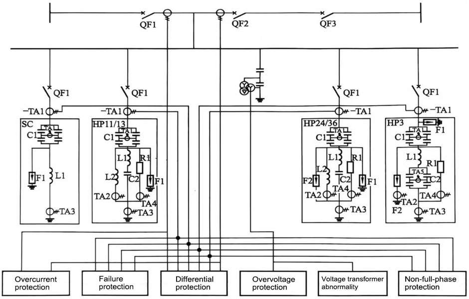
This paper introduces the large group filter protection using the ratio braking bus differential protection principle, and its principle is shown in Figure 1.
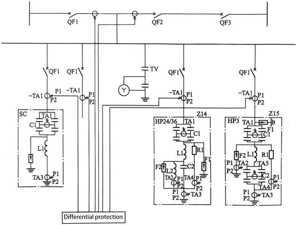
Figure 1 Schematic diagram of large group filter bus differential protection
The protection adopts phase-by-phase comparison of differential current, which is only sensitive to the power frequency. During the protection operation, the abnormal TA, TA saturation, and inconsistent TA transient characteristics must be considered (in these cases, the differential protection needs to be locked to ensure no false operation). After the protection is activated, the large group and group switches of the filter are tripped at the same time.
(1) The ratio differential action equation is shown in formula (1):
 (1)
(1)
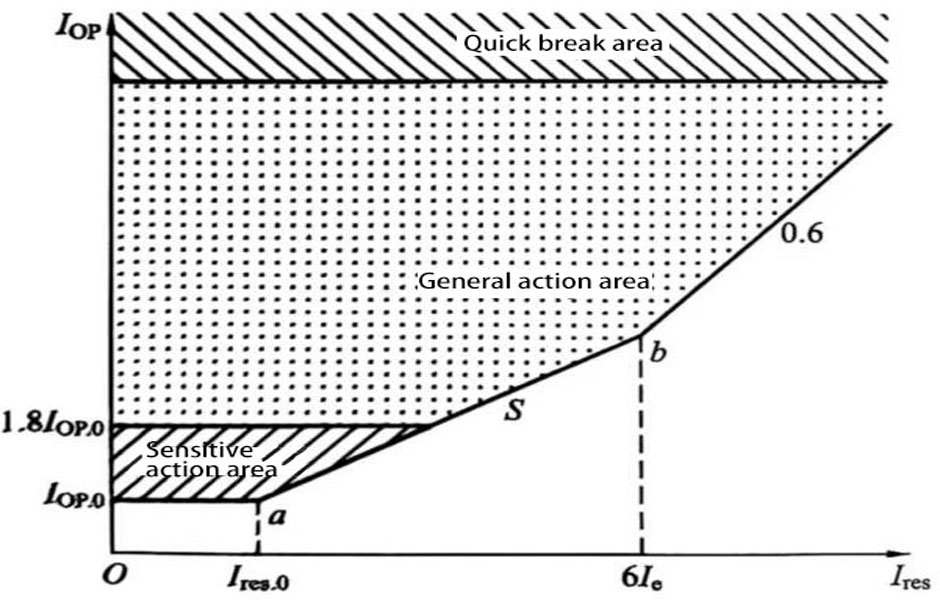
Iop is the differential current, Iop.0 is the differential minimum action current setting value, Ires is the braking current, Ires.0 is the minimum braking current setting value, In is the component rated current, S is the ratio braking coefficient setting value, and the direction of the current on each side is the positive direction pointing to the filter connection line.
(2) The ratio differential protection action characteristic diagram is shown in Figure 2.
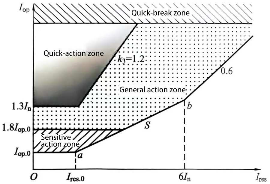
Figure 2 Ratio differential action characteristic diagram of large group filter
3.3 Protection judgment criteria and setting principle
According to Table 14 of standard IEC 60044-1:2003 “Transformer Part 1: Current Transformer”, the error of TA at rated current is determined, and the maximum current error and total current error are calculated based on this. The differential current is considered as the error current to avoid.
(1) Delayed tripping. The typical tripping delay is equal to 200ms.
(2) Immediate tripping. The set value is higher than the rated load current of the capacitor filter.
3.4 Protection action sequence
(1) Section I: Delayed tripping, starting circuit breaker failure protection, locking the AC circuit breaker.
(2) Section II: Immediate tripping, starting circuit breaker failure protection, locking the AC circuit breaker.
4 Large group filter overcurrent protection
4.1 Purpose of protection
The purpose of this protection is to serve as a backup protection for large group lead phase and ground faults.
The protection range is the area between the two current transformers on the large group bus and the current transformers of each group capacitor filter.
4.2 Protection principle and strategy
The protection consists of 3 sections of time-limited overcurrent (section I alarm, section II, section II trip) and 1 section of inverse time-limited overcurrent protection. Each section has an independent setting and delay, which can be set separately. When the current of any phase meets the following conditions, the protection will trip or alarm after a delay.
(1) Time-limited overcurrent element. When the current of any phase meets the conditions of the formula, the protection will trip or alarm after a delay.
![]() (2)
(2)
(2) Inverse time overcurrent element. The large group of inverse time overcurrent adopts the IEC principle, and the general inverse time curve and the action characteristics are shown in formula (3):
![]() (3)
(3)
Where Tb-inverse time constant;
Iset-inverse time starting current constant;
I-TA secondary side current.
This inverse time element is set with upper and lower limits of delay. If the theoretical action time t is less than the upper limit of the inverse time delay, the actual action time is the set upper limit of the inverse time delay; if the theoretical action time t is greater than the lower limit of the inverse time delay, the actual action time is the set lower limit of the inverse time delay.
The action characteristic curve of the inverse time overcurrent protection is shown in Figure 3, and the logic diagram of the overcurrent protection is shown in Figure 4 As shown.
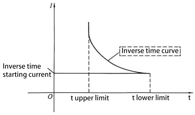
Figure 3: The upper limit of t is the upper limit of the inverse time delay, and the lower limit of t is the lower limit of the inverse time delay.
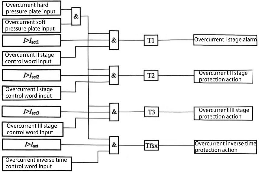
Figure 4 Overcurrent protection logic diagram
Protection coordination: The protection is coordinated with the rated value of the filter element and the overvoltage protection.
4.3 Protection judgment and setting principle
(1) Alarm: The setting of the alarm level ensures that it will not be activated when the system voltage fluctuates normally. The typical value of the alarm level is 1.1 (standard value).
(2) Delay tripping: Delay tripping at 1.3 times the rated load current, the typical value of the delay is equal to 1.5s.
(3) Immediate tripping: This part is used as a backup protection for differential protection. The tripping level is higher than the highest current (inrush current) that may occur in the capacitor filter group, but lower than the lowest short-circuit current level.
4.4 Protection action sequence
(1) Alarm.
(2) Working section: Delayed tripping, start circuit breaker failure protection, lock AC circuit breaker
(3) Section II: Immediate tripping, start circuit breaker failure protection, lock AC circuit breaker
5 groups of filter overvoltage protection
5.1 Purpose and scope of protection
The purpose of this protection is to avoid serious AC continuous overvoltage that damages the AC filter group and parallel capacitor group.
The protection scope is to protect all filters and parallel capacitors in the large group.
5.2 Protection principle and strategy
Measure the voltage of each phase on the filter bus, and compare the voltage between the phase and the ground with the voltage setting value to determine whether an abnormal overvoltage occurs. This protection is sensitive to power frequency voltage and voltage below the 7th harmonic. Its protection principle is shown in Figure 5 As shown.
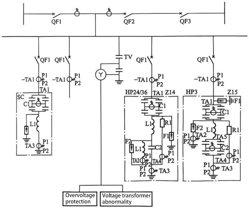
Figure 5 Overvoltage protection principle diagram
5.3 Protection judgment criteria and setting principle
The overvoltage protection action equation is shown in formula (4)
![]() (4)
(4)
Where U is the phase voltage or line voltage of a large group of leads;
Uset is the overvoltage protection setting value.
The typical protection setting value is 1.15~1.5 times the rated voltage, and different action time limits are determined according to different overvoltage levels.
When the protection setting value is 1.5 (standard value), the typical action time limit can be 0.2s. When the protection setting value is 1.15 (standard value), the first group action time limit can be 10s, and the other groups will increase the delay of 10s in turn.
5.4 Protection action sequence
(1) Alarm.
(2) Trip the large group capacitor filter circuit breaker.
(3) Delay tripping the filter group circuit breaker.
(4) Start circuit breaker failure protection.
